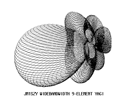

The antenna which a computer was used for optimizing its performance can be seen so often in these days.
I first saw such kinds of articles on Japanese CQ magazine or Japanese Ham journal No.65 in late 80's. I recognized that there was a trial of let's do the optimization of the antenna by using a computer before it as well. However, at that time, a personal computer itself was unfamiliar to general persons like me, and softwares for the optimization of the antenna seemed to be not so good as much as those of the present.
Although I can't remember the contents of the article of Mr. Kato which appeared in Japanese Ham journal No.65 precisely because I left it in Japan, I was strongly impressed by his article -- especially by his thought related to the optimization of the antenna.
At that time, I didn't know even the word of MS-DOS. Thus, I was using his software having the junior of my university help it.
After that, I bought the software called YSIM , and got a free software developed by JA1WXB (MMPC). I have been using such softwares to evaluate many kinds of commercial based antennas or home-brew ones.
Recently, I purchased the softwares well known as "AO 6.5" and "YO 6.5" designed by K6STI, and others. (e.g. W7EL's EZNEC, VE2GMI's NEC4/WIN, SM5BSZ's YOLIN and NEC2 MOD, and WA7RAI's Quickyagi)
As the knowledge of a certain degree related to the antenna design could be acquired by using these softwares, I would like to state my opinion about how to make a computer designed antenna.
If you run some kinds of the antenna simulation softwares, you would find the following facts;
that is, YOU NEVER GET THE REALLY SAME CALCULATION RESULT WHEN A CALCULATION IS DONE BY USING DIFFERENT SOFTWARES.
When you design a new antenna using a computer software, you may be especially anxious as to whether a character in calculation can be actually reproduced properly.
First, these antenna design softwares aren't absolute.
Secondly, even if the precision of the calculation by a certain software is high, an error in the production process of the antenna is inevitable because a human being makes it.
Third, -- as I'm a 6m band (50MHz) enthusiast, I will go on with this story based on the things related to 6m band ---, the elements of the antenna are usually mounted on the aluminum tube boom. When the elements of antenna are close to, or pass through a conductive substance, these electrical length would change. Thus, if you pursue the exactness, it is necessary to compensate the length of each element according to the boom's diameter.
Forth, even if you mount your antenna at the top of your tower which uses conductive substances, your antenna would be affected by your tower, mast, and so on.
As I illustrated above, there are many elements which have a bad influence on the performance of the antenna.
Therefore, I should say that it is almost impossible to reproduce a character of the antenna as calculated.
However, I don't deny the design of the antenna which a computer was used for. If you use a computer software, you can easily expect what kind of the antenna will be constructed. Don't you think that it is big progress when it is compared with the thing before the ages when it was being gone through with by trial and error by the manual operation?
When antenna design is done with the personal computer, you should put in your mind that an error always arises in the calculation result. You should consider that an error always arises even if you do the most of all the means including the element-compensation I mentioned above. When I calculated the character of a certain antenna using different softwares, the frequency that the performance which was the same was reproduced deviated several 100kHz by the case. You may think that these softwares have the possibility that an error could arise that much. Therefore, I think that we should not design an antenna which shows a good performance only at a very narrow frequencies -- I mean that you should not design very sensitive antenna.
I sometimes find persons who are doing misunderstanding. That is, when a person who designed a very narrow bandwidth antenna and could perfectly match it at a designated frequency, he said that he could reproduce the computer designed antenna perfectly. If you have enough experiences in constructing antennas, you could find his misunderstanding.
Yes! To minimize SWR and to reproduce the particular character of the antenna are totally different things. Thus, if you have a software for antenna design which can handle only at a spot frequency, I recommend you check the character of the antenna on other frequencies.
It is generally said that maximizing forward gain of yagi antennas sacrifices good pattern while to gain good pattern sacrifices the forward gain. The same relationships are found among SWR, gain, and pattern. Certainly, if you maximize the forward gain of your antenna, you can send the strongest signal in the forward direction. However, when you receive the weak signal you will lost the chance to make contacts with such weak signal senders because maximizing the forward gain yields the good S/N ratio over the omnidirectional noises. The same thing is applied to SWR bandwidth. You might hear the good reputation of M2 Inc's antennas. Their antennas may fairly put values on the forward gain. However, for example, if you check the SWR bandwidth of its 11 element yagi for 6m, you will find that it keeps a fairly wide SWR bandwidth.(SWR 1:1.5 --- More than 1MHz by YO, and more than 600KHz by AO)
The antenna I will show from now was designed experimentally. Thus, I didn't check its performance on the actual operation. As I run several simulation programs and get nearly same result from them, I suppose that almost same result as the calculation will come out when it is actually made.
The meaning of "the optimization of the antenna" varies for each person who uses it. If you don't have any local station in your neighborhood and any QRM, you may pursue the maximized forward gain. However, as I live in a big city, I must minimize the minor-lobes as much as possible to avoid QRM from nearby stations. Certainly, if I ignore the good beam-pattern quality, I can get the same forward gain with shorter boom length -- maybe under 9 meters.
Many persons used to try to maximize the front-to-back (F/B) ratio. Conventional way to calculate F/B ratio is measured by comparison between the forward power at 0 degrees and the power radiated in the opposite side (at 180 degrees). Maximizing the F/B ratio is certainly one of the methods to reduce the minor-lobes of the antenna. However, yagi antennas often have large back-lobes at the angles other than 180 degrees. Thus, when I designed the following antenna, I took the F/R ratio into account. Both YO and AO provide the optimizating function for the F/R ratio; that is front-to-rear ratio. According to the AO's manual, "AO provides two methods for characterizing power within the F/B region. The first method simply averages power over the region. When F/B is optimized using this method, total power within the F/B region is minimized. This is particularly useful with EME arrays to minimize total earth noise on receive. The second method uses an L4 norm. This mathematical technique is like that used to compute RMS power, but the fourth power and root are used instead of the second. F/B computed using the L4 norm is approximately the ratio of forward power to the power of the peak lobe within the F/B region. When F/B is optimized using peak power, backlobe amplitudes are minimized while maintaining roughly equal amplitude. This method is particularly useful with HF antennas since it minimizes worst-case interference from signals arriving at random rear angles".
When I designed the antenna below, I had set following goals as for F/R ratio.
The following are reasons why I had set such goals.
First, at this time, I use only SSB and CW. However, I hope to use RTTY on 6m in near future. In Japan, RTTY is not allowed under 50.9MHz. Thus, I would like to keep a good average F/R over 1MHz.
Second, as you know, DXs are often heard around 50.110MHz. In addition, in Japan, contest QSOs are often made between 50.250 and 50.500MHz. I'm interested in both DX and contest. Thus, I would like to maintain good F/R ratio between 50.0 and 50.5 MHz -- both peak and average F/R.
The second goal is to keep a wide bandwidth. As I have stated before, if you make a narrow bandwidth antenna, you have a possibility to be bothered by the differences between the calculated result and the actual antenna characters. So I designed the antenna which has a very wide frequency response. Thus, if you round up or down the scales of the antenna I designed, the antenna's character will not change drastically. For example, if you shorten every elements and elements' positions approximately 1 - 2cm, the forward gain at 50.110 which I considered as the center frequency would change only 0.03db in YO's calculation.
Third, I have set a goal to keep a good SWR over the wide bandwidth. The antenna's matching frequency often changes depending on the environment where the antenna is mounted. For example, imagine that you take a 1:1 SWR matching at the desirable frequency setting the antenna at 10meters or so above the ground, and, then, you mount it 20 meters above the ground. The matching frequency often shift above or below the initial frequency. Have you ever experienced such a thing?
I designed this antenna to be matched at 50.110MHz. However, if the matching frequency shift to, say, 49.5MHz or 51MHz, you may keep a good SWR (below 1:1.5) from 50.0 to 51MHz.
I designed this antenna to use non-taper 14mm diameter aluminum tube as elements. I have been unconcerned about the diameter of element and the correction of the length of the tapered element antenna. However, if you use tapered elements, you should seriously consider the element-length correction. The following is the example of length correction (In this example, I'm using M2 6M7's element-length. 6M7 uses tapered elements consisted of 9.5mm and 6.5mm tubes.)
| Taper | 9.5mm None Taper | Differences | |
| Ref | 3054.4mm | 2995.6mm | 58.8mm |
| Ra | 3003.6mm | 2945.2mm | 58.4mm |
| D1 | 2851.1mm | 2793.8mm | 57.3mm |
| D2 | 2845.1mm | 2787.8mm | 57.3mm |
| D3 | 2774.9mm | 2718.2mm | 56.7mm |
| D4 | 2720.9mm | 2664.6mm | 56.3mm |
| D5 | 2701.9mm | 2645.8mm | 56.1mm |
As you can see in the table above, the length of elements changes drastically.
However, the antenna I will show supra, will not be so affected if you use, say, 10mm diameter tubes. (If you use 10mm tubes, the frequency responses will shift about 100KHz to 200KHz. As this antenna has a wide frequency response, it will not be a serious problem.)
Numerical values indicated here is the detailed values calculated with the personal computer. However, as I have said before, you can round up or down these values. For example, the distance between Ref and Ra can be round to 80cm. The half length of reflecter can be round to 1480mm.) Unit here is "mm" ,and element diameter is 14mm.
| Element Position | Element Length(Half) | |
| Ref | 0 | 1476.9218 |
| Ra | 802.6820 | 1435.2050 |
| D1 | 1220.2788 | 1375.2327 |
| D2 | 2251.8193 | 1343.1875 |
| D3 | 3742.7727 | 1321.4492 |
| D4 | 5363.3481 | 1303.5376 |
| D5 | 6832.6636 | 1272.2395 |
| D6 | 8192.5557 | 1300.8397 |
| D7 | 9679.0000 | 1262.5654 |
Here is the characters shown by YO (F/R shows average backlobe power)
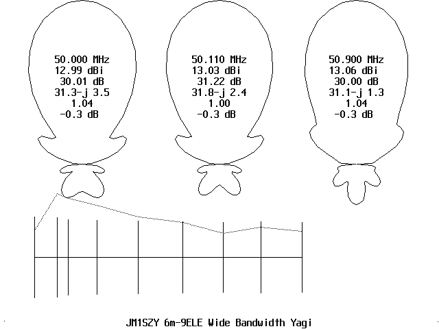
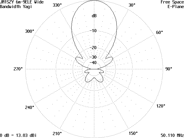
Here is the graphs which show the frequency response from 50.0 to 50.9MHz.
F/R shows front to average backlobe power.
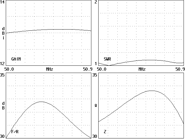
F/R shows front to peak backlobe power.
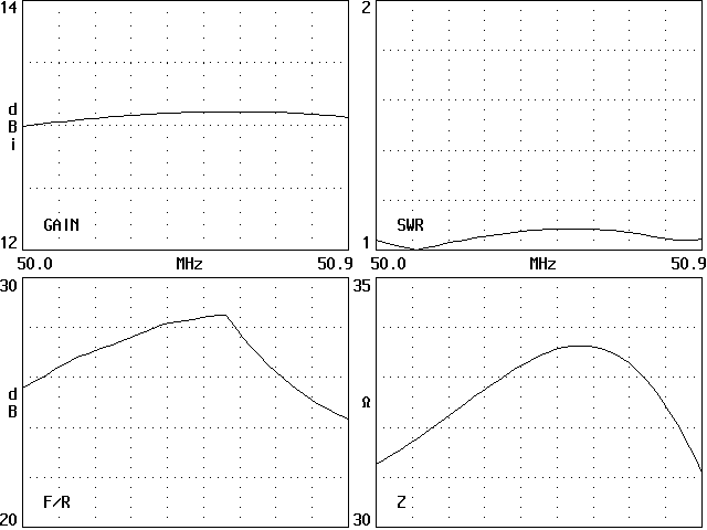
AO calculates the forward gain and F/B ratio at 50.110MHz as following;
Gain=13.02dbi and F/B=31.74db
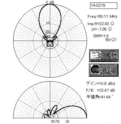
In addition, I checked the character of this antenna using MMPC for Windows95. The following are the graphs and figures calculated by MMPC at 50.110MHz
MMPC indicates the forward gain using "dbd". So, to compare with "dbi", please add 2.15db.
SWR shows the figure when the antenna is fed directly with 50 ohms coaxial cable. So, if you put matching section, the figure will change.
| Freq | 49.0 | 49.1 | 49.2 | 49.3 | 49.4 | 49.5 | 49.6 | 49.7 | 49.8 | 49.9 |
| Gain | 12.41 | 12.48 | 12.55 | 12.61 | 12.67 | 12.72 | 12.78 | 12.83 | 12.88 | 12.93 |
| F/B | 15.27 | 16.02 | 16.83 | 17.69 | 18.64 | 19.68 | 20.86 | 22.21 | 23.79 | 25.70 |
| SWR | 1.56 | 1.5 | 1.45 | 1.39 | 1.34 | 1.29 | 1.24 | 1.19 | 1.14 | 1.09 |
| Freq | 50.0 | 50.1 | 50.2 | 50.3 | 50.4 | 50.5 | 50.6 | 50.7 | 50.8 | 50.9 |
| Gain | 12.97 | 13.02 | 13.05 | 13.08 | 13.11 | 13.13 | 13.15 | 13.15 | 13.15 | 13.15 |
| F/B | 28.11 | 31.35 | 36.08 | 41.58 | 37.49 | 32.68 | 29.56 | 27.39 | 25.82 | 24.67 |
| SWR | 1.04 | 1.00 | 1.04 | 1.07 | 1.10 | 1.12 | 1.13 | 1.13 | 1.11 | 1.09 |
| Freq | 51.0 | 51.1 | 51.2 | 51.3 | 51.4 | 51.5 | 51.6 | 51.7 | 51.8 | 51.9 |
| Gain | 13.13 | 13.10 | 13.07 | 13.02 | 12.97 | 12.90 | 12.81 | 12.71 | 12.59 | 12.46 |
| F/B | 23.86 | 23.35 | 23.13 | 23.20 | 23.62 | 24.47 | 25.91 | 28.28 | 32.46 | 42.82 |
| SWR | 1.08 | 1.13 | 1.22 | 1.36 | 1.56 | 1.74 | 1.95 | 2.13 | 2.21 | 2.10 |
Here are also the graphs which show the frequency response. (by YO)
Please see the SWR. Each graph shows the character at 49.0, 50.110, and 51.4MHz.
When matched at 49.5MHz
When matched at 49.8MHz
When matched at 50.5MHz
When matched at 51.0MHz
As you can see, this antenna will perform well in fairly wide frequency band.